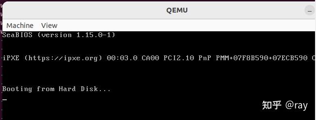
1. 编译文章中的例子,然后制作img软盘,使用qemu运行
没有在bochs中运行,可能会是黑屏,等编写了完整的代码再用bochs试一下。
$nasm boot sect.asm -f bin -o boot sect.bin
$dd if=boot_sect.bin of=a.img bs=512 count=1 conv=notrunc
$qemu-system-i386 a.img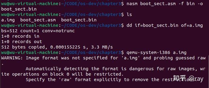
查看二进制文件内容:
$od -t x1 -A n boot sect.bin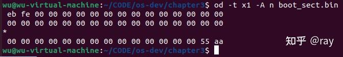
2. 实现操作系统启动的知识点介绍
(1) 16位实模式(real mode)
操作系统都是从real mode开始启动的,然后转换到32位的protected mode。
(2) 中断(interrupts)
利用BIOS的中断(interrupts)来实现字符打印。利用中断号实现对中断的调用。中断号就是中断向量interrupt vector表的索引。下面会用到中断0x10(屏幕)和0x13(磁盘)。
Each interrupt is represented by a unique number that is an index to the interrupt vector, a table initially set up by BIOS at the start of memory (i.e. at physical address 0x0) that contains address pointers to interrupt service routines (ISRs). An ISR is simply a sequence of machine instructions, much like our boot sector code, that deals with a specific interrupt (e.g. perhaps to read new data from a disk drive or from a network card).
来自wiki.osdev.org对Interrupt Vector Table的解释:
On the x86 architecture, the Interrupt Vector Table (IVT) is a table that specifies the addresses of
all the 256 interrupt handlers used in real mode.

The IVT is typically located at 0000:0000H, and is 400H bytes in size (4 bytes for each interrupt).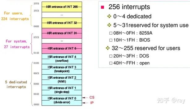
INT 0x10:
AH=0EH: 光标跟随字符移动
AH=0EH/INT 10H 则会使光标位置移动,每显示一个字符,光标会往右移一格,假如已经到最右边了,则光标会移到最
左边并移到下一列,假如已经移到最下面一列的最右边,则屏幕会向上卷动。
AL = 字符
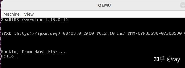
BL = 前景色打印hello的代码:
;
; A simple boot sector that prints a message to the screen using a BIOS routine.
;
mov ah , 0x0e ; int 10/ ah = 0eh -> scrolling teletype BIOS routine
mov al , 'H'
int 0x10
mov al , 'e'
int 0x10
mov al , 'l'
int 0x10
mov al , 'l'
int 0x10
mov al , 'o'
int 0x10
jmp $ ; Jump to the current address ( i.e. forever ).
;
; Padding and magic BIOS number.
;
times 510 -( $ - $$ ) db 0 ; Pad the boot sector out with zeros
dw 0xaa55 ; Last two bytes form the magic number ,
; so BIOS knows we are a boot sector.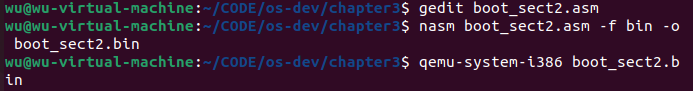
(3) CPU 寄存器(register)
All x86 CPUs have four general purpose registers, ax, bx, cx, and dx, for exactly that purpose.
mov ax , 1234   ; store the decimal number 1234 in ax
mov cx , 0x234  ; store the hex number 0x234 in cx
mov dx , 't'    ; store the ASCII code for letter ’t’ in dx
mov bx , ax     ; copy the value of ax into bx , so now bx == 1234
Notice that the destination is the first and not second argument of the mov operation, but this convention varies with different assemblers.
nasm语法中,第一个参数是目的地;
mov ax , 0       ; ax -> 0x0000 , or in binary 0000000000000000
mov ah , 0x56    ; ax -> 0x5600
mov al , 0x23    ; ax -> 0x5623
mov ah , 0x16    ; ax -> 0x1623
(4) 内存(memory)、地址(address)
BIOS将磁盘的MBR(512Byte)写入内存中的0x7C00的位置。
Why BIOS loads MBR into 0x7C00 in x86 ? - Glamenv-Septzen.net(en)
那怎么定下是0x7c00这个值的呢?那是为了尽量让最多的连续内存空间分配给操作系统,选择把MBR放在内存的最高端方向、另外还需要预留512B的堆栈/数据空间,因此从内存的最高处倒数过来,就计算出了MBR的存放位置:
0X7FFF(5150机器总内存空间32KB)-512B(堆栈/数据空间)-512B(MBR空间)=0X7C00。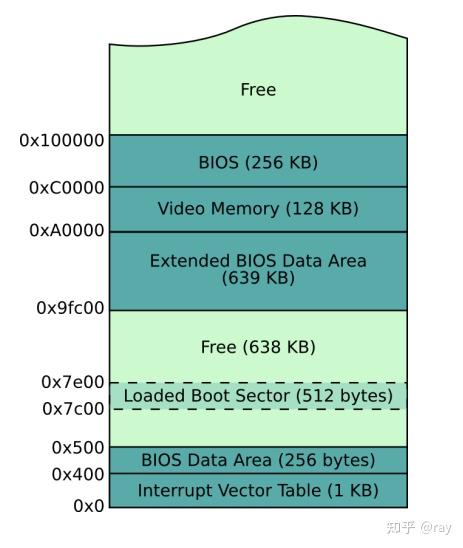
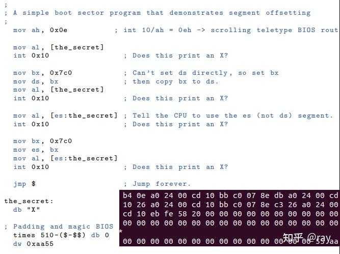
(5)标签(label)
the_secret :
db "X "(6)偏移量(offset)
mov al , [the_secret] ; 中括号表示存储地址中的内容到寄存器中;
the square brackets instruct the CPU to do this very thing - store the contents of an address.
(7)[ org 0 x7c00 ]
(8)定义字符串
db : “declare byte(s) of data”
定义字符串时要以0结尾;
CR表示的是ascii字符集中的“回车”控制符,它的16进制值为0D;
LF表示的是ascii字符集中的“换行”控制符,它的16进制值为0A;
my_string : db 'Booting OS'

my_string : db 'Booting OS',0  ;null-terminating string

MSG_SET_PAGE     db " set page.",0x0d,0x0a,0 ;包含换行回车的字符串
(9) 堆栈
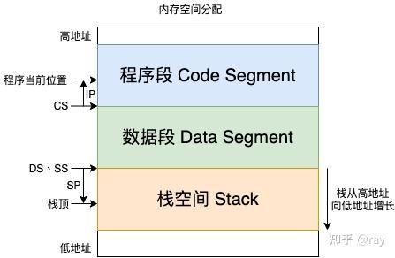
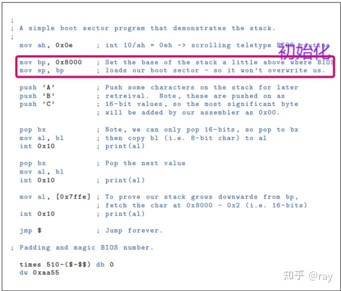
堆栈是向下增长的,即内存地址由大到小的增长。
bp: 栈底;
sp: 堆顶;
初始化: BP指向堆栈的栈底,SP也指向栈底;
push: SP的值减少,BP不变;
pop: SP的值增加,BP不变;
(10)函数
jmp $ ; jump to address of current instructiona. 为什么用函数调用,而不用jmp来实现同样功能?参考文档Page20.
b. call和ret的功能?
答:call类似于jmp的功能,只是在jmp前,将返回的地址压入栈中;ret则是弹出栈中的地址并调到地址处。
However, the CPU provides a pair of instructions, call and ret, which do exactly what we want: call behaves like jmp but additionally, before actually jumping, pushes the return address on to the stack; ret then pops the return address off the stack and jumps to it.
(11)intel A20地址线
以下摘自网络:
A20地址线并不是打开保护模式的关键,只是在保护模式下,不打开A20地址线,你将无法访问到所有的内存(具体参考下面的第5点)
用于80286与8086兼容
用于80286处于实模式下时,防止用户程序访问到100000h~10FFEFh之间的内存(高端内存)
8086模式,A20关闭的情况下,访问超过1MB内存时,会自动回卷
8086模式下,A20打开的情况下,访问超过1MB内存,就真实的访问
保护模式下,A20关闭(始终为0),则用户的地址只能是:0 - (1MB-1), 2 - (3MB-1), 4 - (5MB-1),我们可以这样设想,A20为个位数(以1MB为单位),如果它始终为0,你永远不可能让这个数变成奇数。
保护模式下,A20开启,则可以访问全地址,没有奇偶MB的问题。
(12)Segments
1. CPU运行在16位模式的时候,寄存器是16bits,最大可以访问的指令地址是0xffff(64KB=66536 bytes)。为了增大空间,引入了段(segmentation)的解决方案。
2. 段寄存器(segment registers):cs, ds, ss, and es。
cs寄存器:存放当前正在运行的程序代码所在段的段基值。
ds寄存器:存放数据段的段基值。
ss寄存器:存放堆栈段的段基值。
es寄存器:附加段寄存器。
在数据移动、搜索、比较这类指令中,DS 对应 SI,ES 对应 DI。这个时候,DS和ES就不同了,前面的表示源,后面的表示目的地。
3. 按照段进行编址最让人迷惑的地方就是相邻段之间的重叠,即不同段和偏移组合的地址可能指向同一个物理地址。
4. 最大访问地址:1 MB (0xffff * 16 + 0xffff).
默认在数据段ds;
a. Instruction mov ax, [0x45ef] would by default be offset from the data segment, indexed by ds.
b. So if we set ds to 0x4d and then issue the statement mov ax, [0x20], the value stored in ax will actually be loaded from address 0x4d0 (16 * 0x4d + 0x20).
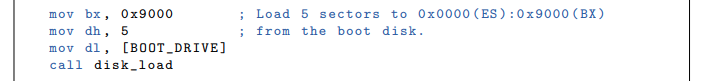
(13)读写磁盘
输入参数:
dh:需要读取多少扇区;bx:数据写入的目的地址
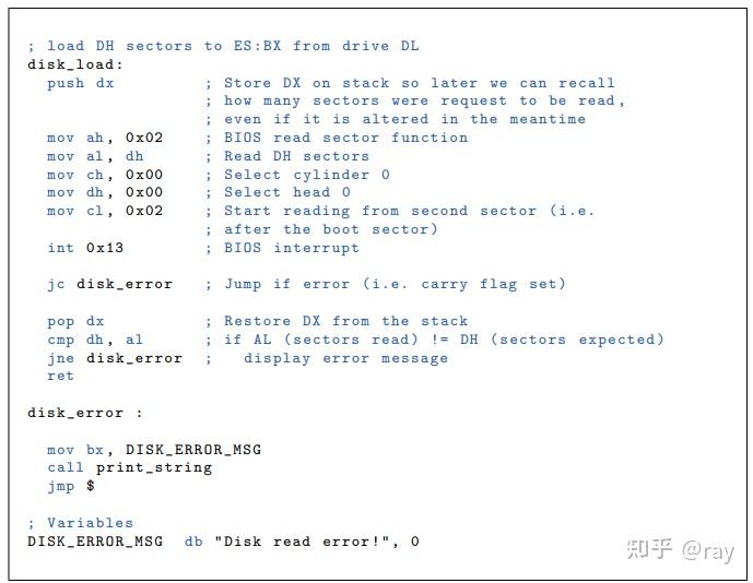
函数内存参数:
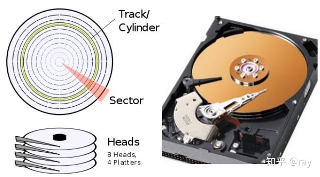
ah:调用读扇区的函数; al:读取扇区的个数; ch:cylinder索引; dh:head索引;cl:sector索引;
Cylinder-Head-Sector (CHS)
以下是从网络中摘取的一些资料:
利用BIOS读写磁盘:int 0x13
BIOS中断INT 0x13中,ah=0x02,即为读磁盘扇区到内存,利用这二号服务即可读入setup模块。
调用此功能将从磁盘上把一个或更多的扇区内容读进存贮器。因为这是一个低级功能,在一个操作中读取的全部扇区必须在同一条磁道上(磁头号和磁道号相同)。BIOS不能自动地从一条磁道末尾切换到另一条磁道开始,因此用户必须把跨多条磁道的读操作分为若干条单磁道读操作。
入口参数:
AH=02H 指明调用读扇区功能。
AL 置要读的扇区数目,不允许使用读磁道末端以外的数值,也不允许使该寄存器为0。
CH 磁道号的低8位数。
CL 低5位放入所读起始扇区号,位7-6表示磁道号的高2位。cl=开始扇区(位0—5),磁道号高二位(位6—7)
DL 需要进行读操作的驱动器号。dl=驱动器号(若是硬盘则要置位7)
DH 所读磁盘的磁头号。dh=磁头号
es:Bx—>指向数据缓冲区 ES:BX 读出数据的缓冲区地址。
若出错则CF示志置位返回参数:
如果CF=1,AX中存放出错状态。读出后的数据在ES:BX区域依次排列

 支付宝微信扫一扫,打赏作者吧~
本文链接:https://kinber.cn/post/6287.html 转载需授权!
推荐本站淘宝优惠价购买喜欢的宝贝:

 您阅读本篇文章共花了: